We have gears!........
Having packaged up all the bits and bobs I have been acquiring and poasting them off to Thunderace, things have been moving ever forwards.
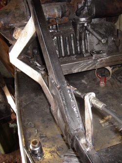
Within a couple of hours of DHL dropping the bits off the gear selector was installed and selecting away.
The gearshift on the Metro is cable operated, but the stock cable is a bit short, so a section of solid bar stock was added to the end of the cable to allow it to reach and then the outer of the cable was bracketed to the frame rail.
The plan now is to mount the selector quadrant under the dummy tank ahead of the pilot.
Better view from t'other side
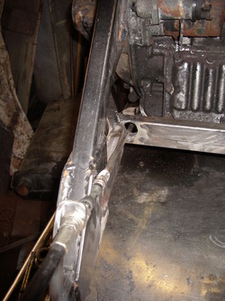
Better view from the other side. A hole was put in the cross member before it was welded in place ( the cross member, not the hole)
A 'Rotabroach' cutter (borrowed from Worf) was used and then a stub of thick walled tube was welded into the hole to put the strength back.
In the words of TA, "Sure I could have bent the link rod a little to go above or even bellow the cross member,
but the straightest line was through it, so hence it has to go through."
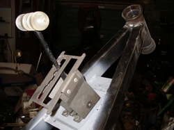
The gear quadrant is now bracketed into the frame so the lever comes up through the dummy tank, TA turned up a rough little acrylic Tee shift handle, (he calls it "rough" -- I think it's great!).
The wide neck that came as standard on the frame has been cut away and a neck to suit the RM80 yoke has been attached. Some gusset plates and steering stops will be added in due course.
The wide neck that came as standard on the frame has been cut away and a neck to suit the RM80 yoke has been attached. Some gusset plates and steering stops will be added in due course.
Sneak preview of the exhaust exit plate ....
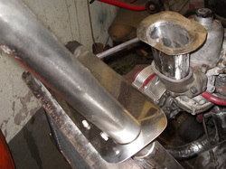
Here you can see the neat little stainless bit to make the holes where the exhausts go through the body nice and tidy, rustled up on the mill by Martin ( Hayabusa Rider ) in a few hours here at the weekend.
( new toy to him, never used one before, but seems to be pretty good! ).
TA is planning to cut similar stainless escutcheon plates for all the holes in the body.
You can also see a little stainless top hat to connect air into the carb up to flat to the body, knocked up by TA at the same time.
( new toy to him, never used one before, but seems to be pretty good! ).
TA is planning to cut similar stainless escutcheon plates for all the holes in the body.
You can also see a little stainless top hat to connect air into the carb up to flat to the body, knocked up by TA at the same time.
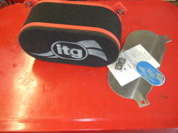
As mentioned earlier, I was considering getting an ITG filter. The alternative I had in mind was a chromed pancake filter housing for a bit of bling. Anyway, in the end I thought the "bling" at that end was taken care of, courtesy of those rather impressive pipes! So --- ITG it was!
I was going to get a JC10/100 from Merlin, coming in at around £60 with a base plate, then saw this JC30/100 on ebay at £21, including the base plate (this model from Merlin is more like £75 with the plate).
In retrospect the JC10 would have been dwarfed by the pipes, the wider JC30 looks much more the business.
Just for a change ... The Front End
You might recall ... this is the front end, as it came off the BMW: Unit leading links, factory adapted for the ATE calipers (which we ain't using!). So, as few mods were callled for .......
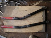
TA took a few measurements, did a few bits of trig and worked out how much he needed to reduce the bend back of the fork legs down to,
and then used the hydraulic bender in reverse to reduce the bend in the leg,
So here are the two legs, one now with reduced bend back and the other as made by Unit Sidecar;
and then used the hydraulic bender in reverse to reduce the bend in the leg,
So here are the two legs, one now with reduced bend back and the other as made by Unit Sidecar;
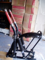
So having reduced the bend back on both legs, he then narrowed the brace which goes round the back of the wheel to suit the yokes and removed a few of the brackets which will not be used, (see little pile to the left of the re-assembled fork).
This has produced a much neater set up. Ok bit more work required before we are happy with them yet, but the basic geometry issues have been taken care of.
For a very informative post on the geometry of triking, see this article put up by Thunderace on the BTW forum:
http://btwukonline.co.uk/index.php?topic=1482.0
Still a bit ugly at this stage, and the tar like plastic coating doesn't help much with looks!
Not exactly sure, what the coating is. At first I thought it was powder coated, but it looks more like a plastic dip!
Unit Sidecars web site claims: "Finish is black, in hard wearing chemically cured paint on an acid etch primer".
but then the picture at the top of that same page is this one;
Unit Sidecars web site claims: "Finish is black, in hard wearing chemically cured paint on an acid etch primer".
but then the picture at the top of that same page is this one;
And they, very obviously, are silver not black ( and don't look so bad in silver ) whereas every pair TA has had in his workshop (and every set I have seen) have been finished in a gloopy black goo.
yes it looks very like powder coat to me too. But it seems to be coming off quite easy enough.
yes it looks very like powder coat to me too. But it seems to be coming off quite easy enough.
Rear suspension & running gear started.......
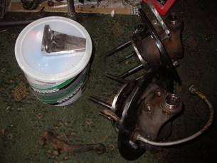
Ok next bit, making suspension arms:
TA stripped the Mini hubs of ball joints and unbolted the steering arms, then cut a pair of angle brackets from heavy rolled section, drilled them the same centres as the steering arm; giving a good root fixing for assembling the arms. Now to make up the eight brackets required to attach the suspension arms to the frame,
TA stripped the Mini hubs of ball joints and unbolted the steering arms, then cut a pair of angle brackets from heavy rolled section, drilled them the same centres as the steering arm; giving a good root fixing for assembling the arms. Now to make up the eight brackets required to attach the suspension arms to the frame,
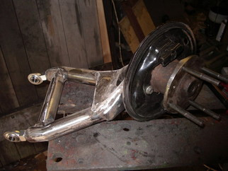
To the Mini upright from the previous picture TA then attached a couple of short pieces of thick walled tube, which have had a 5/8 UNF threaded insert welded in their ends.
So, by screwing a pair of rod ends (Rose joints) into the ends, we have the first suspension arm;
needs a good clean up with the grinder, but that can come later when the lower shock mount has been welded on, for now you get the general idea.
As with most of the previous trikes built by TA, he is sticking with the semi-trailing arm type design, preferable from the point of view that it's simple enough to be able to get the geometry right, and, since both toe-in and camber increase with suspension compression, is 100% stable. Kind of useful for a trike, especially as (some) trikers have a tendency to be "adventurous".
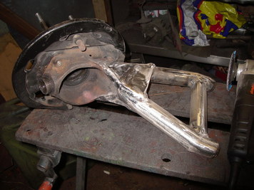
OK, it doesn't look quite so good from the back, (the rusty mini hub lets the side down), but it does show how the bits go together to make a nice strong little suspension arm.
What you are not seeing is the jig TA made out of box to hold the bits straight before welding them, or the piece of bar stock he turned down at one end to fit inside the hub splines to make sure the centre line of the hub bearings lined up with the centres of the rod ends, that's just how things are done.
So, it's simple in one way when you look at it as an old Mini front upright, two bits of tube and some heavy rolled section, but trick as hell when the result is a cute little beefy semi-trailing arm.
A substantial piece of ironmongery: Thunderace's usual method is make up the rear suspension to a track narrower than stock, then just hack the shafts down to suit.
'sThat is easy. Here however we want to use the full stock length of the shafts. It's surprising how much more difficult that has turned out to be!
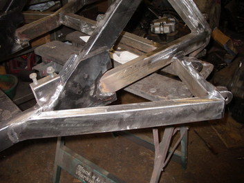
It has taken a good week and and half longer, but finally he has been able to add the extra structure to the frame to take the suspension arms;
So on each side a short section of box is joined to the frame outboard of the rear cross member, it's outboard end is then connected back to the frame with a longer section of the same box, attaching where the mid cross
member is on the inside of the frame.
The rod end joints of the arm thus bolt in to the brackets on the short piece of box.
All that's needed now is to make and fit the shock mounts and that will be rear suspension done.
Soon be on wheels !!!! Talking of which ... When Central Wheels got the hub they discovered the bearing was shot as well as the thread on the retaining ring being hacked about. Until the wheel comes back ( which should be anytime now) I won't know if it's one or both of the bearings, but it will make sense to replace both. After a few discussions with Central the rim is now alloy and the spokes stainless steel. Just a tyre to settle on now. Avon Roadrunners look OK to me, but so do Continentals .... we shall see ......
'sThat is easy. Here however we want to use the full stock length of the shafts. It's surprising how much more difficult that has turned out to be!
It has taken a good week and and half longer, but finally he has been able to add the extra structure to the frame to take the suspension arms;
So on each side a short section of box is joined to the frame outboard of the rear cross member, it's outboard end is then connected back to the frame with a longer section of the same box, attaching where the mid cross
member is on the inside of the frame.
The rod end joints of the arm thus bolt in to the brackets on the short piece of box.
All that's needed now is to make and fit the shock mounts and that will be rear suspension done.
Soon be on wheels !!!! Talking of which ... When Central Wheels got the hub they discovered the bearing was shot as well as the thread on the retaining ring being hacked about. Until the wheel comes back ( which should be anytime now) I won't know if it's one or both of the bearings, but it will make sense to replace both. After a few discussions with Central the rim is now alloy and the spokes stainless steel. Just a tyre to settle on now. Avon Roadrunners look OK to me, but so do Continentals .... we shall see ......
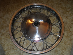
Wheel arrived today ... to say I am pleased with it is an understatement!
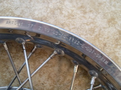
Akront Morad non-valanced 17" alloy rim, 2.15 width.
New filler arrived too -- excellent bit of kit :-)
Akront Morad non-valanced 17" alloy rim, 2.15 width.
New filler arrived too -- excellent bit of kit :-)
 |
 |
With the tyre ........
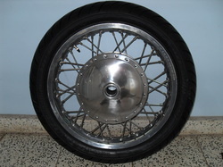
With the tyre fitted .... went for an Avon Roadrider in the end.
110 / 80 - 17 ... directional tyre, so plumped for brake going on the right of the wheel (offside)
110 / 80 - 17 ... directional tyre, so plumped for brake going on the right of the wheel (offside)
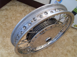
Reassembled .....
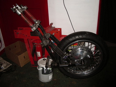
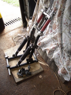
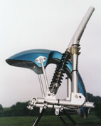
So if you take the yokes from a Japanese kiddie crosser.........
add the after market British made sidecar forks from a German tourer .........
and a hub from a Classic Norton laced into a Spanish rim ..........
and spend a little time on the lathe from Cardiff turning up a few bits ........
one ends up with a front end that looks like this;
Ok needs a little adjustment here and there, but all the bits mate nicely with no issues, very pleased with how that all went together, not saying this Frankenstein creation would win any beauty contests, but it does look like all the bits were meant to fit together, which is a reasonably good trick given the seven plus thousand miles which separated the various bits at time of manufacture, and the size difference of the machines for which the parts were originally intended.
Speedo Drive fitted.
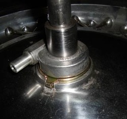
In classic form we have a front wheel that has no provision for a speedo drive !
So the simple way out of the hole is to modify parts and fit the wheelbox made to fit a harley. I sourced a suitable speedo drive (narrowest I could fine to fit a sportster). TA stuck the drive up in a four jaw chuck and took 84 thou off it's integral spacer, and then machined a section of the wheel spacer so that the end of that fits inside the bore of the speedo drive unit. He then cut a notch into the wheel hub so the tang of the speedo drive has somewhere to engage, and presto a speedo drive is thus fitted.
Longest part was cutting the notch in the wheel, which can only be done by hand.
and ....... Back to the suspension ....
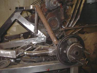
TA cut two lengths of tube and drilled two 1/2" through holes on 11 1/2 centres in each
to act as 'lock up bars' in lieu of the coil over shocks for the time being.
Then cut four shock mounts from suitably sized box section, and then welded the lower shock mount to the suspension arm and the top was joined back to the frame with a short piece of 50 x 30 rectangular section,
and a 25mm tubular strut down to just forward of the engine mount.
( rusty things are the lock-up bars )
