Engine Mounts

Cut from this: 3 x 5 angle ( 5/16 section ), which, apparently, eats angle grinders!
This first one, on the nearside, attaches to the same four studs as the stock near side mount did in the Metro.
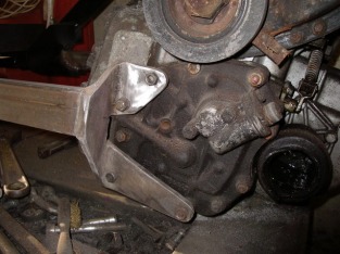
Now the offside motor mounts:
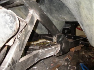
For the metro application Leyland added two angled pressed-tin ears to the torque converter cover,And they did not delete the holes in the cover where the single mount had been previously, for both Mini and Allegro fitments, they did admittedly stop fitting the thread inserts, so TA first off drilled and tapped a suitable lump of steel and welded it inside the cover to be able to use that mounting point, which then again took a nice heavy bracket cut from heavy angle with a couple of M10's to hold it.
Next for the forward ear of the Metro mount system, he cut a nice thick plate to fit, drilled and tapped it M10, screwed in and then welded two M10 studs into the plate, so it nuts up to the mount, and the plate then was welded to a brace cut from more of the 25 x 50 box .
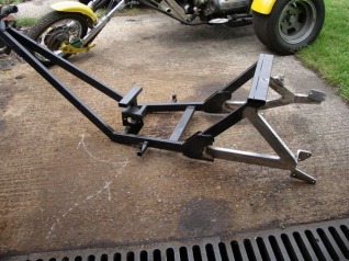
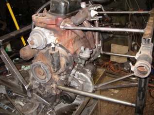
This is what the frame now looks like with the A Series mounts in place.
A cross member will be added in when the suspension arms have been made and fitted. But for now we have a Phoenix frame that takes the A plus motor and transmission.
A cross member will be added in when the suspension arms have been made and fitted. But for now we have a Phoenix frame that takes the A plus motor and transmission.
Frame meets Body
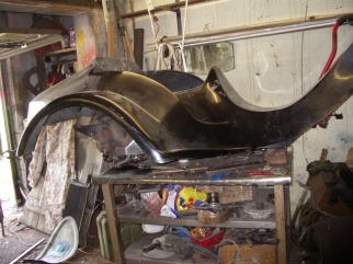
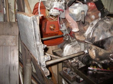
Frame and motor re-assembled on the bench, and time to check the body fit.
Quick look inside the body in front of the motor to see what room there is for tank, battery, linkages, electrics etc;
With plenty of room in there I decided (after much prodding from TA) to get a used Rialto petrol tank (come in eBay, once again!). This gives us around a 5 gallon capacity.
With plenty of room in there I decided (after much prodding from TA) to get a used Rialto petrol tank (come in eBay, once again!). This gives us around a 5 gallon capacity.
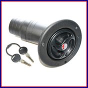
Whilst mentioning the fuel tank I will add here the fuel filler neck and cap I went for. This was £58 (plus the dreaded VAT) from Europa Spares. I was originally going to go for an alloy finished aero cap which was around the same sort of money, but decided on the black in the end (practically on the toss of a coin!).
Thoughts are still "in the air" as to where to place it: Plan "A" being on the right hand side ahead of the rear seat but behind the front. Plan "B" is to put it where a bikes filler would be (if we had a tank up there).
Thoughts are still "in the air" as to where to place it: Plan "A" being on the right hand side ahead of the rear seat but behind the front. Plan "B" is to put it where a bikes filler would be (if we had a tank up there).
Another change of Tack.....
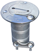
Having bought the above fuel filler and offered it up to the trike, it isn't what I wanted (Just too plasticky and a bit of a disappointment). So ...... whilst searcing around I fell upon this. It's a deck filler neck and cap for a yacht.
Checked with the friendly people at VOSA and they reckon it fulfills the regs. This is what they say:
"The first thing that has to be considered here is that of it meeting with
the minimum Design & Construction requirements for a fuel cap. This is
covered in Section 14 of the MSVA Inspection Manual and as such states
under para 8;
"Check fuel filler caps for;
a) presence,
b) security,
c) and ensure that when closed, they form a positive seal which does not
allow fuel to leak."
The term "security" in b) above does not mean that it has to be a lockable
cap in that respect.
The second thing that you will need to consider is that for Exterior
Projection requirements in relation to where this fuel cap is going to be
located. I assume that the trike is as such "unbodied" and that the fuel
tank is in the usual position in front of the rider. That being the case
then the requirements for this location are covered in Section 8 (Exterior
Projections - Unbodied Vehicles) of the MSVA Inspection Manual and states
under para 4;
"Check that the rear edge of any filler cap located on the upper surface of
the fuel tank (which is likely to be struck by the rider in the event of a
collision);
a) does not protrude more than 15mm above the surface and is smooth or
perceptibly spherical,
b) does protrude more than 15mm above the surface and is fitted with a
protective device."
However, if the trike is a "bodied vehicle" then the projection
requirements for such are detailed in Section 9 of the Inspection Manual.
Under the General Requirements heading, it states the following;
" 1) Check that all hard parts on the external surface have a radius of
curvature of at least 2.5mm.
2) Check that all projections less than or equal to 5mm in height from
the external surface have a blunted edge.
3) Check that all projections more than 5mm in height from the external
surface have a radius of curvature of at least 2.5mm"
Therefore, so long as the fuel filler cap meets with the above requirements
(and from looking at the photo, I do not see any obvious issues here) then
it appears to be acceptable in that respect."
So, there you go.
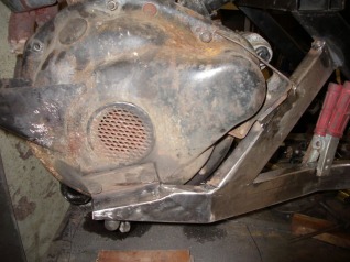
Loads of space, then there is the space behind the motor, this is the view from the floor looking up; Again plenty of space to get a radiator and an exhaust or three (more on that later), oh, and an alternator, but it's not exactly cramped. Looking up at the SU carb you can see that we only need to extend that neck an inch or two and then the air could come in from above the rear deck. Looking at something like an ITG foam filter. I am sure there will be more on that later, when the time comes to cut the hole and fit whatever I have bought.
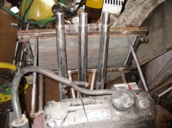
Body back off and mounting a Radiator.
What is needed is some structure behind the motor to support a radiator, that's going to be the Mk2 Metro rad, which is on it's way. So TA cut a piece of 1 inch square box at 26 inches, which can be trimmed it to length later, and then this was attached this to the engine/trans unit with a few little brackets and struts, a temporary radiator from the stock in the shed was found and sat where the Metro rad will eventually go. Just a couple of stays for the top needed now :-)
The Pipes, the pipes ........
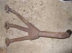
Another eBay find .... a Cooper three branch exhaust manifold .... which will be sacrificed to give us three rearward pipes. Each pipe will have a Beetle style tailpipe inserted to mute the sound a tad.
The exhaust part of the cast-in-one manifold has been cut away to leave just the inlet part,this then allows a Cooper three branch tubular exhaust manifold to be fitted, and which has been cut off at the collector.
This gives us three nice pipes to build the exhaust system from, and plenty of room between the back of the engine block and the radiator in which to do so.
You will also notice that the top of the rad has acquired a couple of bracing struts to hold everything nicely in place.
This gives us three nice pipes to build the exhaust system from, and plenty of room between the back of the engine block and the radiator in which to do so.
You will also notice that the top of the rad has acquired a couple of bracing struts to hold everything nicely in place.
And ... an alternator
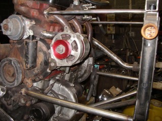
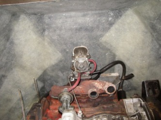
Alternator bracket made ( using a borrowed alternator from another trike just for the time being ). Note also the bottom radiator pipe roughed out, just needs finishing. Going to look real good -- seems a pity to cover it all (well, it will once I have cleaned up and painted the engine and ancilliaries).
As you can see from how the bottom of the timing case air/oil mist separator is chamfered to miss the belt run, Leyland made things so the alternator can be fitted this side of the block as well as the other side where it lives on most applications, some times one can even find the genuine Leyland bracket which mounts the alternator on this side, however the usual Lucas ACR16/17/18 units fight for space with the mechanical fuel pump, so one is then stuck with ditching the mechanical pump and going to the less reliable electric fuel pump, which is not a great answer, so the other way round the problem is to use a physically smaller French or Slovenian alternator, for which there is no stock Leyland bracket which will just bolt on, but the body is short enough to just miss the fuel pump.
Ok it's a little more work to make a custom bracket, but to be honest the Lucas unit was not great, Paris Rhone, Femsa, or Iskra are a better choice. ( And look so much nicer too ! )
It may seem like an odd time in the build to be attacking these kinds of things,but, according to TA, it's better to get all the fiddly stuff done early rather than leave it till later. At this stage it's easier to make pipe runs reasonably neat, rather than wait till later and find that only a length of that ugly convoluted Gates hose is going to make the connection 'tween water pump and rad.
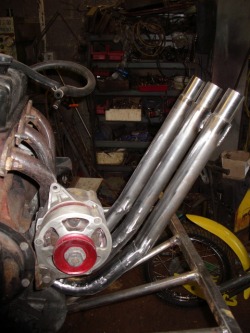
Thunderace laboured over two days to join three 1 inch and a 1/2 tubes to the sawn off Cooper manifold and get to a point where the three arrive in a nice neat row.
Stainless silencers/tail pipes which will plug on the ends of those tubes, and which will be the only bits that show, are yet to be made, everything else will be hidden by the body.
Stainless silencers/tail pipes which will plug on the ends of those tubes, and which will be the only bits that show, are yet to be made, everything else will be hidden by the body.
From another angle ......
Those pipes from the top of the engine looking backwards, showing how they will clear the radiator.
In Thunderace's words,............. "part of the game here is to get some length into the pipes, so hence I have come down to the diff case before turning the pipes up to angle back over the top of the rad, which meant to do the three used just short of ten feet of tube, so by the time I have added two feet of stainless tube on the end of each, with the Cooper manifold as well, that gives me a total length of just short of six feet from each exhaust valve to end of pipe."
I think they are going to look awsome!

Tail pipes added. Beetle tailpipes are going inside to mute the sound a tad.
