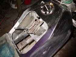
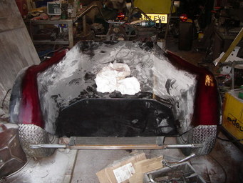
Trial Body fit ......
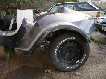
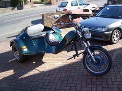
Stuck 225 60 14's on wheels found in the back garden on the studs and rolled it outside to check the fit of the body and get a measurement for how far the arches need to be moved back to centre the wheels in the arches.
Ok looks a bit odd with the 14's but just to get a measurement was fine.
So, it seems the arch has to be moved aft by a mere 5 1/2 inches, and on 225 tyres four and a half inwards, which matches perfectly with the slope of the rear quarter panels, so yeah it will all work fine, or at least it would be damned easy with 225's, but we got to go at least 245, which will be slightly more involved, but hey that's just how the game goes.
And with the arch moved a little ....
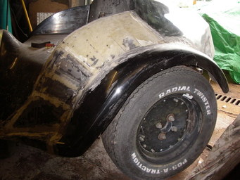
A bit more filling and rubbing down to be done, but looks far better ... remember it's sat on borrowed 14" wheels at the mo ... will fit the 15" Raceways a treat :-)
Whilst the gel coat on the shell leaves a little to be desired the glass lay up is superb. Anyway the gel coat will disappear under a coat of paint eventually.
Whilst the gel coat on the shell leaves a little to be desired the glass lay up is superb. Anyway the gel coat will disappear under a coat of paint eventually.
The rear wheels and tyres .....
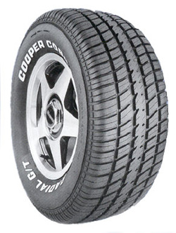
Decided to go with these tyres on 10 inch wide rims.
The arches on the body have been cut both sides to bring the wheel centre and to pull the outside edge in a little so the arch doesn't overhange too much.
Because the rear quarter panel slopes that part of the arch fits straight back on with a piece chopped out, the front part is slightly more involved as the panel below the rear seat has to curve slightly more now to meet the arch, but it's not that hard to slice the glass and get the pieces to line up.
The tyre size of choice at the moment is 265-50-15, which will be sat on Raceway 10 x 15 Alloys ... picture below .....
UPDATE ... was literally about to order the rubber when a pair of General Grabber tyres (tires?) came up on eBay at £60 the pair !!!!
The Coopers were coming in at around £90 each (Grabbers are £120) ... so saved 120 sobs on buying the Coopers ... so the rubber now is definitely 255 - 60 - 15 General Grabbers !
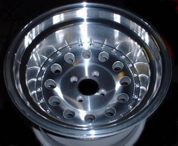
A pair of these will set the trike off nicely :-)
Bit of thought on Electrics and suchlike
First off .. managed to get a second hand Honda Superdream left hand switch cluster for the princely sum of 55pence .... good old eBay :-)
Anyway .... "Plan A" was for me to play with the wiring over the winter, but, guess what? It turns out Thunderace is a dab hand at wiring !!! Bearing in mind I was going to have to work in an unheated garage with no power, over the dark winter months, it would have taken me months to wire up, so TA got that job too!
He will do all the wiring in his usual choice of multi-core YY control cable with no joins or taped up mess with an IP54 aluminum box for all the relays and terminals so no wet can get in, AMP 'Faston' crimps the same as OEM in top range cars, not those awful red/blue/yellow things from Halfords, it's better to do a quality job and know you are never going to have problems with any of it than skimp.
Been on a buying spree........
    |
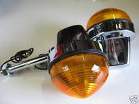 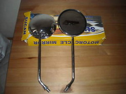 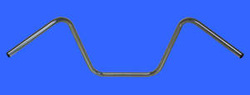  |
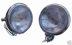
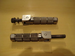
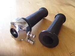
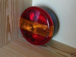
Been storming ebay this week to try to get the last few things needed for the trike. As you can see from the pictures above, I have done quite well: 5 3/4" Bates style headlights, two with bottom mounts to go on a light bar flanked by the "Lucas" style indicators. Couple of nice round mirrors, pair of footrests in stainless, Twist grip so's we can go ! A set of nice handlebars --- worked out a 13" rise should do it, 53" wide with around 5" pull back should give a comfortable riding stance. Hamburger rear lights ---- not the prettiest, but one of the pair has a window in the bottom to light the rear number plate, so simple to do and MSVA friendly. Might play around with LED things once the test is done and dusted! Finally, in my little picture gallery is a waterproof 12V socket, to mount just to the rear of the front seat and power my heated thermals in winter ( possibly a cool box in the summer !).
I have also purchased the master cylinder from Europa. So all on my list for now are the rear shocks and a brake lever.
Have also spent the morning in the garage trying to spruce up the tyres I bought through eBay. Where the guy had them on the wrong way with a tight suspension set up, the raised white lettering had taken a bashing. I tried building a few bits up with silkaflex, but it won't stick too well :-( Anyway, after that had cured I went over the lettering with a white tyre pen. Not convinced they look great --- letters are now, if anything, TOO white! But, I am sure they will tone down !
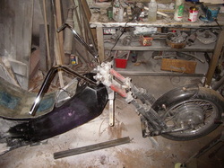
Meanwhile Thunderace has been working on ....
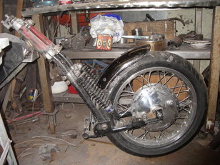
Repositioning the front shock mounts so the front end "springs" more as it should. Old mounts need to be ground off and tidied a bit.
The front mudguard has also been cut down to fit.
The front mudguard has also been cut down to fit.
....and getting dusty ......
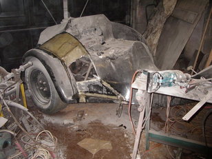
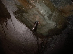
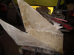
Getting the offside wheel arch glassed back to the body again, needs a bit of work here and there to get the shape.
TA has cut the panel into sections the same as he did on the nearside, then cut each one down, ground away the top layers of gel coat and glass, and then re-fixed each back in place with a layer of roving wetted out well with plenty of resin.
once he has the rough shape he will flip the body over,
grind away the inside and then re-build the shell up with multiple layers of mat.
Rebuilding the shell ....
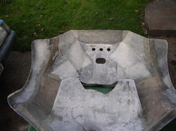
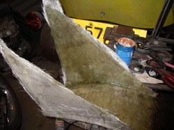
As you can see TA has ground back all the joins and rebuilt up the thickness with mat and resin, so it's all effectively one piece and nice and strong again.
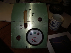
While the body was out of the way he drilled and tapped the fixings for the instrument panel, and screwed that in place with the gearshifter poking up through the slot, this tidies up round the shifter nicely, and means the body comes off with out a load of dis-assembly.
While the body was out of the way he drilled and tapped the fixings for the instrument panel, and screwed that in place with the gearshifter poking up through the slot, this tidies up round the shifter nicely, and means the body comes off with out a load of dis-assembly.
TA has also been milling out the holes in the instrument panel. So, got a big slot for the gear shifter, and holes for ignition switch, fuel gauge with idiot lights, and a hazard flasher switch. As yet the outside is still rough and the piece of aluminum still has the protective green plastic stuck to it.
 |
 |
On the inside you can see again where TA cut a section out of the body and then rejoined the sections by grinding down and then building up the thickness again with mat and resin. You got to love GRP for how easy it is to cut, chop and rebuild !
 |
 |
Bars on for a trial fit .... all good, gives a nice easy reach. Front bar for the headlighta and indicators has been put in place too.
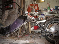
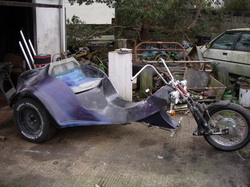
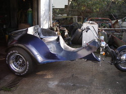
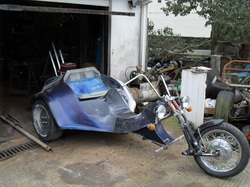
From the side at a low angle you get a better view of the stance of the machine.Also you can see the pipe which runs from the filler neck in the front of the dummy tank back to the Reliant tank under the seat. The open bottom might yet be panelled in, but you got to get down pretty low to see up in there...
Anyway it sits nice, better than the stock Phoenix ( lower, more body rake, chopper style ).
Bit more work still to do on the body, and TA needs to weld some structure to the frame to take footrests, and then we are on to wiring (or, at least TA is)!
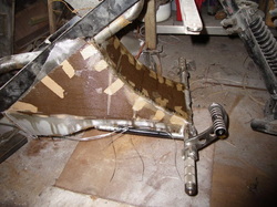
Footrests
The stock Phoenix footrest arrangement hung from a bracket under the headstock, which of course was cut off ! This bracket also had the mounts for the pedals and the brake master cylinder, but this being an auto box and hence only the one pedal is needed!
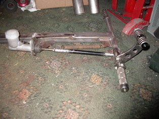
It still means a footrest bar and some arrangement to drive a master cylinder needs making.
So TA turned down some inch bar stock to fit into some inch tube, taped it M12 to suit the footpegs and then welded the parts together to form the footrest bar,
Used some 8mm plate to make a bracket for the master cylinder, and then turned down some more bar stock to make the ends for the brake rod. Welded that into the ends of a suitable piece of tube, and sure enough, after a few days of cutting, turning, tapping and welding, we have something that looks like the picture here; Ok from this angle it's hard to see, but the every thing is lined up, the brake rod is spot on the bore axis of the cylinder, aim is to get the best mechanical advantage, and hence the best brakes possible. ( Yes I know from that point of view concentric chopper style forwards don't make a lot of sense, but they look right, ok, go with it ).
If the weather ever gets warm enough again, TA is planning to make a glass fibre spoiler to fit the space between the front of the frame and the forwards, this will then cover in the master cylinder and keep the dirt out.
 |
 |
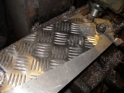
Today TA cut some shapes out of diamond plate on the bandsaw, run the edges on a homemade linisher (washing machine motor with emery paper glued to a large circle of thick ply wood ! ). He reckons every workshop should have one and it should always be home made and involve an ex washing machine motor ! Anyway, he drilled them and milled the area around each hole flat.
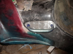
Then he shortened a pair of disabled handrails (Many thanks to Worf from BTW who made the suggestion and supplied the handles) and removed the mounting flanges, shaped the ends and welded a threaded plate in each end to bolt it in place, a piece of stick on tread grip to go where your feet go will finish the job in due course.
So that's the passenger footpegs. (A person either side and they make decent handles too! ).
Talking of wiring ...
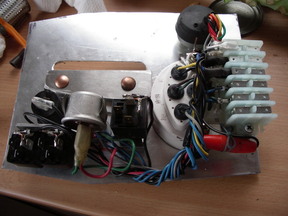
It's been too darned cold to do any more work on the body shell for a few days, with over a week of sub zero temperatures the resin was just taking forever to harden and so TA decided to get on with the wiring.He cut a couple of angle brackets to secure the fuel gauge/idiot light cluster to the panel, putting the various holes in the panel on the mill (makes for a neater job, and allows one to put in the anti-rotation flats for things like the ignition switch) so the hole for the gauge is a nice tight fit on the case of the gauge, but it's best to bolt the thing in too.
Then he drilled and tapped a couple of brackets to mount a strip of six terminals off the same screws. The terminals are RS part number 425-415, they come in packs of ten and you just clip together as many as you need. Again makes for a neater job, and means the cables which will run off to the lights and things can just plug on to the terminals. Then he cut a little aluminum angle bracket to create an upstand to mount three relays,
and set about hitching it all together. Still a bit more to do, but that's most of the panel wired and nearly ready to fit.
Switch Re-wired
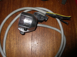
While still sat in the warm at the table TA stripped all the switches out of the CB/CX switchgear (which I had spent hours sanding the black coating off, to get to shiny alloy), un-soldered all the old manky Honda wires, and then soldered a nice new length of multi-core in. The cable being used here is sold as 'YY' control cable. It's a 'Robotic' flexible which will stand constant flexing and
can be obtained by the metre in various sizes and numbers of cores from any electrical wholesaler. To get from the handlebars to the instrument panel TA allowed a metre and a half, which was all of two pound fifties worth of cable. It looks neater than the stock Honda wiring and means there will be no joins or horrible taped up mess running down the bars.
While all the switches were out of the cluster the two case halves were given a light buff with a calico wheel.
New Rear End ... phwooaaar !
Finally the sun came out !
So at last TA has been able to get back out to the workshop to do more work on the body, ( No one actually likes spending hours blocking back filler, but sure goes faster if the stuff actually hardens the same day ).
Obviously where he cut the wheel arches off and then re-attached them further back on the shell there was a little work required to ensure the body still looked like one piece.
Most of it was built up in glass, so a minimum of filler was required, and then said filler was built up, a little at a time, to get the curve to run as close as possible to as the shell was before it was chopped around. Yeah looks ok, day well spent.
The brackets for the rear lights were tacked in place while working at the back, so as far as brackets for lights goes only something for the forward facing marker lights now has to be put in place and that will be all the brackets for lights done.
 |
 |
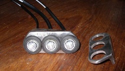
The only bit, it seems, which is not that greatly impressive on this kit is the way the body is supposed to attach to the frame. It looks like the idea is that the body is only held on in three places by through bolts ( possibly with very large flat washers on the outside ? ). Well as you can guess TA was unhappy with that'
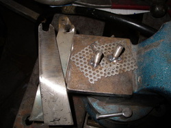
So he welded some short lengths of studding to pieces of perforated steel and cut some strips of stainless, drilled the end, and then cut to form a fork ( He actually did four of each but two looked plenty for the picture )'
The forked pieces of steel were welded to the frame and the studded bits of perforated bonded to the underside of the body with polyester resin, then once that set overnight a few layers of glass roving were applied over each, well wetted out with more resin.
Enough room has been left to be able to put a rubber washer on the inside against the body and a big flat washer between the underside of the nut and the fork.
This should make it reasonably easy to just back off the nuts a few turns and lift the body straight off, and it looks reasonably neat.
While we have the 'glass out ....
We wanted to get as far away from the stock Phoenix front foot rest arrangement as possible.
So not only is the footrest bar mounted via a bar running horizontally forward from the main part of the frame, as opposed to the usual arrangement of dropping it down, but we are also going to have a little bit of body work covering in the master cylinder, brake light switch and generally tiding up the look.
So to get the rough shape TA has just taped cardboard in place,
and then covered that in glass roving, Bit rough and ready for now, but aim is to get something roughly the right shape, and then trim it down to get the shape and fit. Now just going to let that harden over night and then build some more layers tomorrow, until we have the shape we want.
 |
 |
The piece was left, weighted down in a water butt for a couple of days, so the cardboard used to form the rough shape was easy to remove. This then gives the basic shape as a very thin shell in roving.
Next a few layers of mat were built upon the inside to add some strength;
let that harden over night and then just need to refine the shape a little and re-trim it.
Next a few layers of mat were built upon the inside to add some strength;
let that harden over night and then just need to refine the shape a little and re-trim it.
First "proper" airing
Sun finally came out, so we had out forst proper airing. As you can see, she sits a little lower than stock and a little longer.
The seat base at the back has acquired a little bulge over the distributor, but this will be hidden when upholstered (if a little uncomfortable for whoever is perched that side!).
Those forks just HAVE to be silver of some description!
Still on "gash" wheels at the moment
The seat base at the back has acquired a little bulge over the distributor, but this will be hidden when upholstered (if a little uncomfortable for whoever is perched that side!).
Those forks just HAVE to be silver of some description!
Still on "gash" wheels at the moment
But ....
.... while she was out we just had to try the new wheels from Raceways (with those ebay tyres). Fills the space nicely :0)
Side by Side
 |
 |
Here you can see the stock Phoenix (green beastie on the left) compared to ours on the right. Our rider is a good few inches lower, Chopper style and, due to the leading links the wheel at the front about 7 inches further forward.
Nearly there ....
Decided to pop on some daytime running, or marker, lights. So. got hold of half a dozen bright white LEDs from the Bay of E, which are designed to mount directly on the body panel. However, since we are aiming to keep connections between frame and body to an absolute minimum (so the body can be lifted clear without having to disconnect anything) TA fabricated more brackets so they can be mounted on the fram, just below the body, and are, when off, barely visible.
Another look at that rear end ...
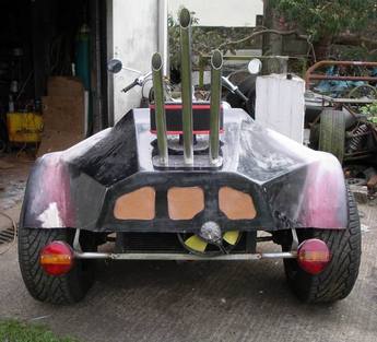
Whilst waiting for a lift from TA's workshops to my garage for final titivating, upholstery and paint, TA decided to cut some ventilation for the rad. After mulling through loads of ideas, from holes spelling various words, through musical fret holes and even a full Austin style chromed grille, he decided on the simple act of repeating the theme of three. What looks like hardboard in the pic is, in fact Gold Expamet, like the speaker grill used to be on real old radio sets. It's metal that has had a huge number of slots punched in it, and then the slots expanded to form like diamond shapes. You have to make sure you put the stuff on the right way up and the right way round because if you don't it looks terrible. The 'look' only works one way round.
